Created by: Kevin Lassley
Date: November 16th - 20th, 1998
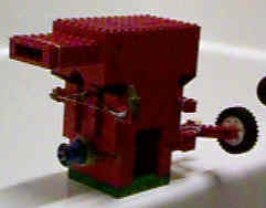

This little engine was built by my brother, Kevin
Lassley. He has always had the knack and and patience to really refine
his LEGO creations and even when something he builds doesn't work quite
right or just plain doesn't work, it *AWLAYS* looks great (as you can see
in this photo.) If you look very closely in the center of the
picture, you can see the little parrot from a LEGO pirate set. For
some reason, Kevin added it, and as usual, his flair for something different
turned out to be quite cool as now the engine doesn't seem "right" without
the little "watch-parrot" on board.
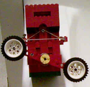
This is the flywheel side of the engine. Since I hogged the Technic motorcycle wheels for my engine, Kevin was forced to come up with a different solution for a flywheel - this one works even better than mine. You can see the little parrot off to the left of the cylinder. Also notice the rubber band that acts as a valve spring (this is the exhaust side.) Kevin's building technique is obvious here as he used curved arch pieces underneath each valve port and built this engine all out of the same color blocks where ever possible. This engine even featured a "Hemi" style design for awhile which was a domed head mated with a domed piston. I thought it really helped the engine to flow better but Kevin disagreed so he returned it to its normal flat head configuration. Personally, I think if we had run it on an air compressor instead of relying on our breath power, we could and would have noticed an increase in power and maybe even RPMs. At any rate, under breath power, this little engine sounds pretty wicked - it almost sounds like a diesel and has a definite power kick. With a shorter throw than the first prototype engine, this little devil really wraps up - I can't wait to try it on an air compressor!
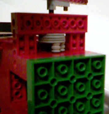
I took this close up in an attempt to better illustrate how the valve lifters were created. They are double pulleys on an axle with a half rivet half axle piece in them. Then 2 little collars are slipped on. There are three rivet/collar assemblies per lifter which gives a full 180 degrees duration. There is one added trick to this engine that Kevin made - the intake and exhaust valves are not perfectly timed 180 degrees from _each other_. There is a slight overlap - much like advancing the timing on a normal V8 engine for more power. This was done by experimenting with the relationship of: the pulleys to the axle AND the collar/rivet assemblies to the pulleys. Each time it needed to be changed required some minor disassembly of the engine - not fun but worth it!
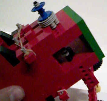
Putting these photos side by side allows you to see how the valves operate as well as a glimpse of the crankshaft and connecting rod somewhat. Notice how in the left photo, the collar/rivet assembly is just about ready to push open the valve and in the right photo, the valve has just been raised about 1/8". Look closely and you can see how the rubber band has been stretched. You can tell this is the intake side of the engine because as the connecting rod is being pushed up, this valve is closed (left photo). This would mean the other valve is open because the air must be vented somehow. In the right photo, just before the piston hits the top, the intake valve is opening, getting ready for a blast of air. The exhaust valve is shut on the other side of the engine. This opening of the intake just before the piston hits Top Dead Center, gives this engine lotsa power with the tradeoff being that you've got to get it spinning pretty good before it'll actually run well. This is much the same reason why a souped up V8 will sound like, "loppity loppity pop pop loppity pop" at idle, but once it's opened up and running hard, it makes all kinds of power. Amongst the racing crowd, it's not uncommon to hear someone say, "He's got a cam in it." (Referring to the loppity noise at idle.)
The photos on this page were taken with a Kodak DC20 set in HQ mode.