Created by: Kevin Lassley
Date: November 20th - 22nd, 1998
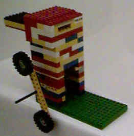
This little wonder is quite the ingenious design. I'm still somewhat baffled as to how Kevin thought it up and he even admitted that he is surprised it worked. Like the previous 3 designs, this engine will run in any position - upside-down, right-side-up, sideways... it doesn't matter. But the one thing that this engine does that the other 3 can't - it can run forwards AND backwards.
You'll notice right
away that there are
no external valve assemblies or cams. In comparison to the
previous
3 designs, you can see the similarities though, such as the
flywheel, the
intake and exhaust ports, and the crankshaft. But how does
this engine
run apparently without any valves? Well the secret is that
the valves
are INSIDE the cylinder and are triggered by the piston - a very
unconventional
design to say the least. The valve assembly actually forms
one wall
(a sealing surface) of the cylinder and as the piston hits the
extremes
of its travel, it hits stoppers that are located on the ends of
the slider
valve. The slider is dual acting - meaning that when
the piston
pulls the slider valve (either up or down), the ports are
automatically
switched into the correct position - either in the "intake open
exhaust
closed" position or the "intake closed exhaust open" position.
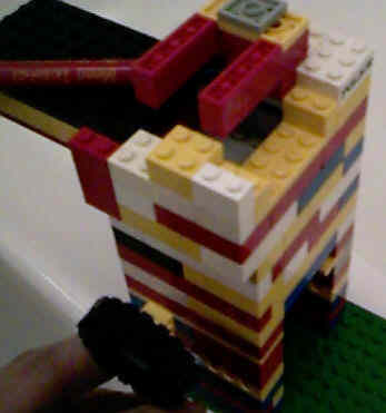 Here I removed the head of the cylinder to reveal the "secret" of
the internal
slider valve design. The valves are actually pulled out
father than
they would normally travel. The two red 4x2x1 pieces are
"level" with each other. The intake and exhaust ports are NOT
level or straight across from each
other as is the case with the previous 3 engine designs. When the
valve is either all the way up or all the way down, it will have
either port in the correct position to keep the engine running.
Here I removed the head of the cylinder to reveal the "secret" of
the internal
slider valve design. The valves are actually pulled out
father than
they would normally travel. The two red 4x2x1 pieces are
"level" with each other. The intake and exhaust ports are NOT
level or straight across from each
other as is the case with the previous 3 engine designs. When the
valve is either all the way up or all the way down, it will have
either port in the correct position to keep the engine running.
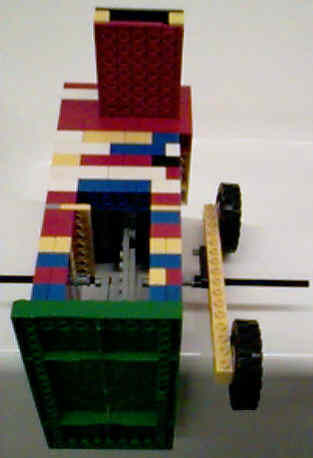
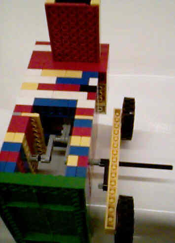
The intent of these photos was to show the bottom part of the valve and how the piston operated it. Unfortunately, the pictures were deeply shadowed in the area I wanted you to see. However, it still illustrates the full travel and motion of the whole crankshaft/connecting rod/piston assembly. This engine also has a longer stroke than the previous designs because the valve operation is dependent upon the piston travel. The long stroke makes for a slower running engine but with the benefit of a lot of torque. If all these engines were set up to power something, I seriously believe this engine, although winning no races, would win a longevity award - it's a very simple and reliable design which surprisingly, uses a bare minimum of LEGO Technic parts.
When building an engine like
this, everything (and
I mean EVERYTHING) has to work with the other components in
harmony..
At first, this sounds like a statement that would qualify me for
the Masters
of the Obvious award but think about it. The travel of the
piston
has to coincide with the travel of the valve. If the valve
got pushed
up too far, it would bust out the top of the cylinder. If it
got
pulled down too far, it would rip off the bottom stopper of the
valve or
break the piston. Also, your piston and valve travel may
work okay
but then the valves may not line up with the ports correctly,
causing the
engine to not run at all. This requires either modifying the
cylinder,
the piston travel, the valve travel, or all of the above.
Changing
one part of the engine more often than not requires modifying the
whole
engine so that everything works together. This is the case
in real
life as well - often modifying one part of an engine can require
modifying
many other parts of the engine so everything works together in
harmony
- once again demonstrating that LEGO can teach real life lessons.
The photos on this page were taken with a Kodak DC20 set in HQ mode.